Introduction
When it comes to building design, it's a forgone and obvious conclusion that one of the goals is to keep the outside out and the inside in. This is called creating the building envelope, and one primary purpose is to provide a safe and comfortable environment for the folks inside the building.
The challenge, of course, is that Mother Nature plays by her own rules, and many times the outside doesn't stay … well, outside. Elements like wind and water batter a building. Temperature shifts swing from freezing to baking and back again. Then there's the manmade factor of noise, most often the sound of traffic in parking decks and adjacent streets.
And if we think about it, expansion joints can be a big failure point … think of slicing a building all the way through – like a layer cake – and one can easily see how the building envelope gets opened to the elements.
This white paper will focus on waterproofing and lays out the materials and methods needed to ensure exterior expansion joint systems help keep Mother Nature at bay.
Section 1: Defining the “water” in Waterproofing
When it comes to sealing the building envelope, one of the primary concerns is water. And most often we think of rain.
Over the last decade or more, we've seen increasing instances of dramatic, extreme weather. Certainly one of the largest and worst examples would be the flooding in Houston, Texas, during Hurricane Harvey in August 2017. After landfall on August 25th, that weather system "hovered" over Houston and Southeastern Texas, spanning almost seven days and produced more than 50 inches of rain in some areas. Another would be Ellicott City in suburban Baltimore, which had two 500-year floods in 3 years. Such weather phenomena are almost forcing meteorologists to throw out their old playbooks, and start afresh.
If we apply the broader term "moisture" starts us down a much more expansive path. We begin to realize moisture can include temperature-induced condensation, fog, drizzle, light-to-moderate rain, and wind- driven rain (thunderstorms, hurricanes, and typhoons.)
In Northern regions, for 4-5 months of the year, moisture means snow. There can be melt that happens as snow comes in contact with a warmer surface, and that water in turn seeks to find its way. In addition, when expansion joints are involved, the weight of snow load is an engineering factor that must be dialed in to the design. Another cold weather risk is ice damming – water freezing in roofing drainage channels, building up and forcing liquid water to flow under and around flashings.
Section 2: Applications
Mixed Use Structures
A growing trend is the construction of mixed-use buildings that may combine retail, parking, office and residential space. Additionally they may incorporate splits lab plaza or piano decks to provide simple open space, or that could be for restaurants or hospitality events.
Application – Stadiums
Given their vast size, stadiums are another special case. There is great variability between the club level, concession areas and the "bowl" itself. The same load issues bulleted above apply.
In our project working on SunTrust Park in Atlanta, a meeting with the head of facility management was punctuated with his emphatic statement, "No foam seals!!"
The reason: His crew uses high-pressure washers to clean up the chewing gum, spilled beer and other messes left behind once the last pitch is thrown. It's not rocket science to figure out the pressure washers would cut a foam expansion joint seal to shreds in short order.
The pragmatic demand of the facility manager rang loud and clear, and the longevity of the joint systems installed will serve the park well for decades to come.
Rooftop gardens and pools
These two specific features can be summed up with the statement: Water, water everywhere. Again, two crucial tie-ins are essential:
- Roofing systems
- Drainage systems
Section 3: Product Options
Closed-Cell Foams
Closed cell foams are absolutely watertight and do not allow the moisture to enter the body of the foam. This is the best application for horizontal runs where water could pool. These are tougher to compress but can be placed under tension (or expand) well.
The other key advantage of closed-cell foams is that they take well to heat-welding of seams. This renders a monolithic installation that reduces risk of water infiltration.
A good rule of thumb: Limiting foam seals to application with a joint width of no more than 8 inches (200mm) or smaller is good practice. Use of foams for expansion joints larger than 6" leads to two things:
- Exceeding the foam's performance characteristics. Plus, the weight of "super-wide" foam seals can lead to sagging in vertical applications.
- Exponentially higher costs compared to other expansion joint cover solutions – i.e., a four-component system with face seal, rails and back seal.
We offer a word of caution regarding Open-cell Foams. Yes, these products do allow for flow-through of water vapor. Like many exterior veneer systems, if moisture becomes trapped in a wall cavity, building systems allow the moisture to wick out. This is a good quality and a major focus to eliminate potential mold issues in vertical applications. And that is the caution: Open-cell Foams should be employed only in vertical installations, where gravity can wick water downward.
Architects should also be aware that Open-cell Foams for expansion joints come in a maximum lengths of 5 feet, and because they are not heat-weldable, caulk must be used at the seams. This can introduce a future failure point as well as higher periodic inspection and maintenance costs should the seams need to be repeatedly re-caulked to prevent leakage.
It's also important to know that while in a compressed state all foams look the same. We would argue that specifications calling for foam seals made with "monolithic manufacturing methods" will avoid product failures and claims down the road. Architects should look closely at the seal's construction, and ask questions of the manufacturer as to the seal's make-up and the watertightness of seams.
Waxed vs. Wax-Free Foam
Heavy wax impregnated foams that help keep joints watertight have been in use for about 50 years. However, some consider the addition of copious amounts of wax as old fashioned, and we would agree … up to a point. Today, we view a 2-3% wax impregnation as the best alternative since it drastically increases the hydrophobic properties of the foam and extends the seal's lifespan.
Water squeezing out of a non-waxed foam seal … once the silicone face is compromised, you can call this a sponge
So what if the specifier chooses to forego wax impregnation? Plain foam can act just like a sponge (as shown in the image here). In addition, plain foam assumes an unrealistic expectation of perfect installation of the silicone face in manufacturing and field perimeter caulk seals to keep the foam protected. If the face silicone seal itself is damaged – say, by the tip of a caulk gun jammed between the foam and wall or deck material -- leaks will occur. With wax impregnation, the foam seal will remain watertight even if the silicone face seal is compromised, in good measure because wax doesn't dry out.
Compression Seals
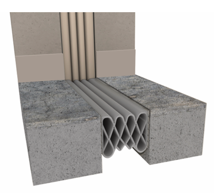
As their name implies, compression seal joint systems are installed into a joint block out and absorb movement and flexing through compression of the seal. The material is also an excellent option for exterior application where waterproofing is required.
These seals are best employed for heavy pedestrian and moderate vehicle loading. Proper use of 2-part epoxies ensure solid adhesion to the deck, and heat-welded seams ensure watertight performance. Nominal joint width for these systems maxes out at 3 1/2" – 4 3/8" (89-111mm).
Building aesthetics can be enhanced through the use of colored compression seals. No more, "You can have any color as long as it's black."
Hybrid Compression Seal Systems
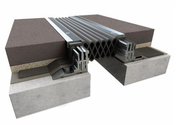
As we already discussed in the Application section on Mixed-use Structures (pp. 2-3) where plazas and piano decks are part of the design, tied-in waterproofing is critical to avoided water infiltration into adjacent spaces.
A new hybrid design of compression seal system is delivering a greater level of waterproofing in splitslab construction. The key benefit of this system is in the integrated counterflashing that's employed, which is engineered to channel water away from the joint opening.
Reinforced Vapor Barriers
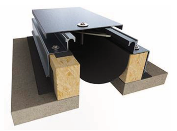
One solution that can be used in certain applications is to employ a reinforced vapor barrier (RVB) to prevent water infiltration or to channel water to drain locations via an integrated drain tube.
The critical factor in installation of an RVB for waterproofing is to apply a bed of manufacturer-approved butyl sealant in the blockout or along the frame along the entire length of the expansion joint. This will aid in securing the moisture barrier to the blockout and provide a watertight seal to prevent seepage around the blockout or frame.
NOTE: Always leave enough drape in the moisture barrier to ensure the system will be able to fully open to its maximum distance without interference from the expansion cover components.
Roof Bellows Systems
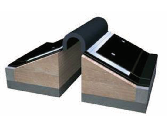
Such system use either an EPDM or a neoprene seal that flexes to accommodate seismic movement. As with counterflashing, the seal must run under the metal flanges to allow water to be shed away from the joint opening. Alos, a compatible, non-reacting mastic should be used to ensure watertight adhesion of the seal.
We’ll add here that with roof systems: Don’t forget the transitions! Meaning: Tying in horizontal and vertical joint systems requires transition covers to help maintain water-tightness. Shown here are several examples of these transitional covers. We’d like to say that architectural drawings and details always cover this ... the reality is that sometimes transition covers and tie-ins are missed.
Waterproof Fire Barriers
We want to talk a bit more about fire barriers, and the need to ensure the barrier stay dry, both before the building is buttoned up and long after the ribbon is cut.
One critical failure point can be in the installation of drains ... two examples of what not to do are shown here – these field-rigged drains nullify any fire barrier warranty. Worse, they compromise the safety of the building and its occupants in the event of fire.
A word about fire barriers & water
The simplest way to say it is: Water kills most fire barriers. In construction, there are usually three possible causes:
- The fire barrier material was left out in rain or snow prior to installation.
- Improper phasing allowed water infiltration through the structure (i.e., before the bldg. envelope was buttoned up).
- Improper barrier drain installation, which is shown above – the field-fabricated drain got clogged and water back-flooded the blanket.
In any case, upon contact with water, the fire blanket is worthless as a barrier, and the fire rating is void. Worse, it creates a huge life safety problem for building occupants.
Well-engineered waterproof fire barriers deliver sound passive fire protection if they:
1) Are wrapped in an integrated waterproof silicone cloth that protects the blanket system and fire rating during and after construction, especially of open structures such as parking facilities and stadiums.
2) Are designed to make seaming and transition assembly as easy and foolproof as possible for field installation.
Note here that the fire-barrier connection is tight to a rated substrate, the seams are consistent and the contractor used proper anchor spacing.
And …
3) Incorporate well-engineered and tested drains tubes that are integral to the blanket system, allowing the barrier to maintain its integrity and fire rating, while allowing water to be channeled to pre-designed outlets.
Section 4: Additional Considerations
Thermal Migration
A driving force toward better overall building insulation is the ever-increasing demand for tighter buildings. Reatting systems like LEED place a high value on increasing the efficiency of buildings when it comes to not only HVAC energy use, but also occupant comfort.
Throughout this white paper, we've been talking about keeping the outside out, and the inside in. And another aspect of sealing the envelope is preventing or greatly reducing the amount of heat the can flow into or out of a structure through façade penetrations.
In our opinion, expansion joint thermal performance is overlooked in the AEC industry as a whole. And in the current state, most consider the Reinforced Vapor Barrier (RVB) as the go-to-standard within expansion joints.
RVBs are a durable membrane that resides within the joint. They accommodate movement, but also prevent the penetration of air, debris and pests from entering through the joint. The picture at right shows an optional drain to channel rainwater or condensation.
There is some minor insulating benefit from vapor barriers, which may actually suffice in certain temperate regions. However, in climates where there are potentials for extremes in temperature -- high heat in Arizona, or bitter cold in Alaska, then an Insulated Vapor Barrier (IVB) should be considered. An IVB is shown below.
As you can see, the addition of insulation within the dual-walled vapor provides a higher R Value – and the benefit, of course, is that the R Value works in both directions – heat or cold don't penetrate the joint, and interior occupant comfort and HVAC performace are better shielded from the outside conditions.
Sound Attenuation
Earlier in this paper, we talked about the rise of mixed-use developments, which increases the proximity of structures like parking garages to adjacent retail, hospitality or residential spaces. Honking horns, slamming vehicle doors, and echoing sounds in a parking deck could be a bothersome distraction to the shoppers, diners and condo dwellers next door.
Thinking a bit more broadly, there are numerous other places where there may be potential for sound or noise to migrate:
- Concert Halls/ Theatres
- Gymnasiums vs. Classrooms
- Manufacturing areas vs. Offices
- Interior partitions at exterior curtainwalls
Another potential source of noise that may disturb workers and others within the buildings are equipment rooms - think machinery like air-handling units in a mechanical room that's adjacent to office space. Oftentimes, expansion joints can run with such spaces or in chase walls nearby to the machine room.
One solution to achieve acoustic dampening is to employ foam seals under architectural joint covers, as shown here. Insulated Vapor barriers can also be employed to reduce sound migration through the joints.
Now, you might be thinking: How much sound can or should be allowed to migrate?
We'll pause here to say that there is an entire body of science, and a profession built around acoustic engineering within buildings, and we won't delve too deeply here for the sake of space.
To keep it brief the rating scale used for sound attenuation within buildings is known as the Sound Transmission Class, or STC. It is an integer value that rates how well a partition or material attenuates airborne sound. As you can imagine, the higher the STC, the greater the amoutn of sound reduction.
A an expansion joint foam seal, like the one shown here, can be rated with an STC of 30 to 52. But there are two things to keep in mind when it comes to STC values:
1) Be sure to carefully read about the joint width that was STC tested. As happens in fire barrier testing, a material that delivered a high STC, say, in a 1" joint, may perform a lot differently when used in a 3 or 4" joint.
2) Beware of claims of the "highest" STC in a rated joint material – the best way to describe this is that a company may claim an STC of, say, 54 as the "highest rating in the industry," implying by extension that any lower STC material is inferior.
The caution is that – to the human ear – the difference between an STC of 54 and another rated at 50 is imperceptible, and it takes sophisticated equipment to gauge the actual difference.
The claim of "highest STC" could be employed to charge premium prices for said material, when in reality, a lower-rated, and less-expensive material may deliver totally adequate sound attenuation. We'll wrap up by saying caveat emptor – let the buyer (specifier) beware.
Wrapping up this section one Product Options … there are numerous systems and products available when considering waterproofing and expansion joints. Oftentimes, we've seen manufactures take a "Foam and only Foam!" stance. This may sound alright, until you realize foam can be one of the most expensive products to use. And as we've shown, foam is not the best alternative in all applications.
Section 5: Steering clear of critical failure points
It starts with the blockout
Blackout: A blackout is a condition present at a joint gap edge to accept different types of expansion joint profiles. Also referred to by regional terminology such as knockout, cutout, and others.
When it comes to expansion joints, this is almost a mantra: It starts and ends with the blockout: the recess in the concrete floor structure or constructed wall system that is formed by the Contractor. Blockouts are created so there is smooth transition across the joint allows alignment of adjacent finished surfaces. Alternative regional terminology might refer to a blockout as rebate, knockout or cutout.
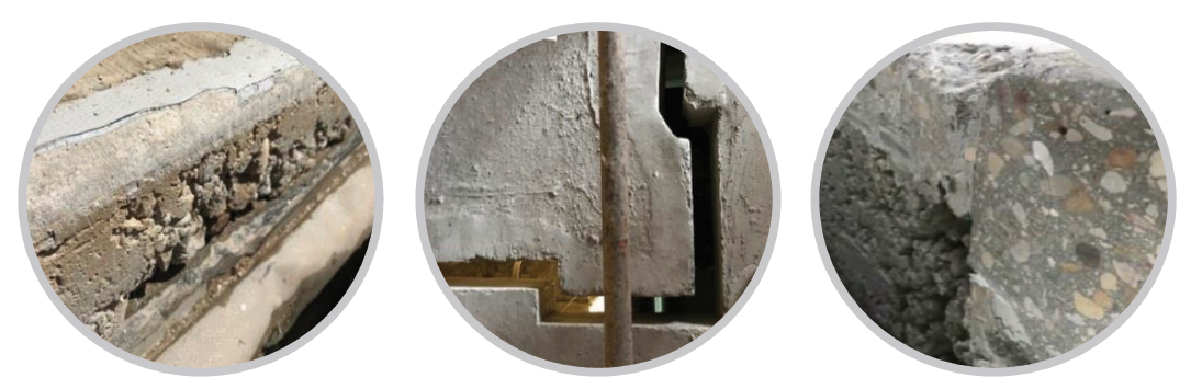
Dimensional variability in the pour can lead to difficulties in installing the expansion joint framing and any waterproofing. And let's talk about cold joints – just the regular gaps that occur with the sequential pouring of concrete. Gaps means leaks when water is introduced.
Then you add in micro-cracks, honeycombing, spalling, form marks and voids can occur when concrete is poured and finished – these concrete faults are shown here.
As hard as it is to believe, concrete itself is not watertight, and leaks will occur, sometimes by something as simple as capillary action.
Tying in and the role of the Trades
Expansion joints don’t exists by themselves; they must be tied in to adjacent systems, which include:
- Concrete, which we covered above
- Wood
- Steel decking
- Steel studs and Joists
- Exterior finish systems
- Masonry
- Glazing
The challenge – and frankly a potential failure point – is the reliance on the skilled craftsmen and women to tie their particular installation into adjacent materials and systems well. For instance, if the glazing specification and bid documents allow the glazing contractor to simply install the frame and glass – and doesn’t demand tie in to say an adjacent waterproof vertical expansion joint, it invites problems.
Same goes the other way, if a waterproofing contractor installs the expansion joint system and doesn’t tie into the window glazing ... you get the point. How the scope of work is bought out can be critical to having a watertight success (pun intended).
While vertical tie-ins are important, nowhere is this process more important than in roofs. For obvious reasons, these large horizontal areas are going to “catch” the most moisture in the form of rain and snow. Waterproof roofing membranes come in two standard forms:
Fluid applied Waterproofing assemblies:
- Hot Mopped Asphaltic
- Torched felt/ asphaltic layers
- Cold applied fluid adhesives
- Petroleum based Built-up systems/ SBS
- Modified Bitumen (MB) asphaltic with SBS modifiers
- Solution > SBS Polyester Flashing
Thermoplastic Single Ply Membranes:
- EPDM
- TPO
- PVC
One of THE most critical questions specifiers must ask: Is the counterflashing on the expansion joint system compatible with the deck membrane and adhesives being applied?
Tie in of roofing systems with expansion joint membranes is essential to good waterproofing. One failure point can be the reaction and subsequent degradation when roofing materials and adhesives fail to bond with the expansion joint membrane. It is important for the joint membranes to be chemically compatible with the roofing materials. Good detailing by the manufacturer should clearly lay out the recommendations regarding roofing membranes and adhesives that are compatible with the expansion joint counterflashing.
Another caution is: Often the specified membrane will be altered when the project is bought out. Manufacturers cannot be held liable if the Installer and GC do not coordinate material changes, and clear them with the Project Architect.